THESE INSTRUCTIONS ARE FOR THE ASSEMBLY OF THE BARE MODEL OF THE PS3TOOTHFAIRY. IF YOU ARE GOING TO PURCHASE THIS, PLEASE READ AND MAKE SURE YOU CAN FOLLOW THESE INSTRUCTIONS. WE CANNOT BE RESPONSBILE FOR DAMAGE DUE TO MISUSE OR ASSEMBLY ERROR.
The assembly instructions are provided here for the BARE model that allows you to use your existing remote circuit board within the ps3toothfairy. Please make sure that you understand these instructions before ordering and you may want to verify that your remote matches the photos shown. If they do not please Contact Us and let us know so we can work with you. The tools that are needed are really only a screwdriver and a pair of wire cutters. The entire procedure should take less than 10 minutes. You should take the same precautions that you would use when working on a computer with regards to static control, grounding, etc. Please do not purchase this model if you do not feel comfortable with the required steps.
-
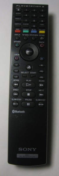
Get your WORKING Playstation 3 remote out and ready for teardown. It should look like the one in the picture. Use it now to operate your PS3 so that you can be sure the remote is in working order.
-

You did test the remote correct? Get out a small phillips head screwdriver and remove the screw indicated in the picture.
-

Insert a small flathead screwdriver into the edge of the remote. Alternatively you can use a thin guitar pick, or squeeze the remote (hard) to release the mechanical latches holding the chassis together.
-
Work your way around the chassis and once you have one side loose, it should "unsnap" easily
-
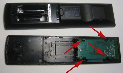
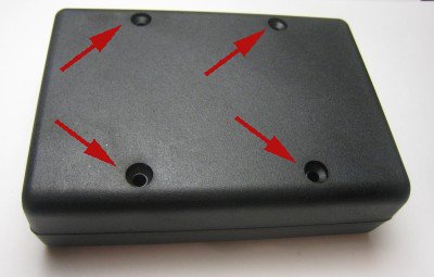
To remove the circuit board from the remote you need to release the four plastic tabs indicated by the red arrows. The circuit board snaps out. Note that the wire "springs" also pop out of the battery compartment.
-

You can flip out the circuit board. The remote has a tendancy to "come apart" because none of the components are held in once you remove the circuit board. The board will still be attached by the FFC (flat flexible cable).
-

The plastic tabs shown by the red arrow release the cable. Simple pull the tabs GENTLY and the black part of the connector will extend outward releasing the cable. Now you can separate the module from the rest of the remote.
-
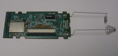
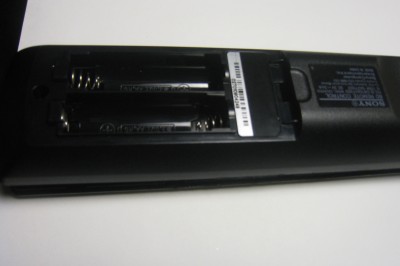
At this point look at your module and compare it to the picture. It should be similar. It is very important that the battery tabs appear as shown in the picture. If not, please stop and send us a message. If they match, then you can continue.
-
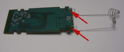
To properly mate with the ps3toothfairy board, put the board upside down (as shown in the picture) and GENTLY bend the pins upward so they are close to vertical. Refer to the next picture if this is unclear. Either use a pair of long nose pliers, or carefully with your fingers. Avoid putting stress on the circuit board.
-
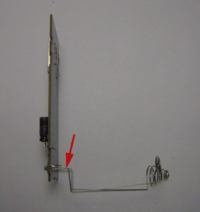
This is what your board should look like from an edge view. The component side of the circuit board is on the left and the bottom of the board is to the right. In the next step we will trim the wires.
-

Using your wire cutters trim the wires leaving approximately 2/3 to 3/4 of the wire protruding from the board. You can use the pins on the ps3toothfairy as an approximate guide to the length. It is always best to leave the wires a little long because you can trim them later. For reference you can see how much I left and cut in the picture here and in the next step.
-

Your modified board should look like the picture above. Make the pins as vertical as possible without putting any stress on the board. They do not need to be perfect, the pins of the ps3toothfairy will accomodate variances in the position.
-
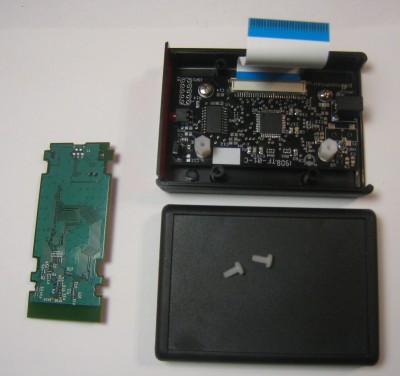
Now you can get out the parts for your ps3toothfairy BARE kit. You should have 4 black screws for the chassis and 2 white screws to hold the circuit board in place. Note that the BARE ELITE kit already has the back panel mounted. DO NOT attempt to remove it.
-
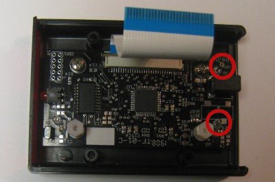
We will attach the pins you just cut to the sockets shown by the red circles. The flat cable will provide the remaining signals for remote module.
-
Attach the flat white cable from the ps3toothfairy to your remote module as shown. The contact side of the cable should make contact with the circuit board. Push the locking connector back in and inspect your connection. It should be nice and straight. If not, then release the lock and repeat the step.
-
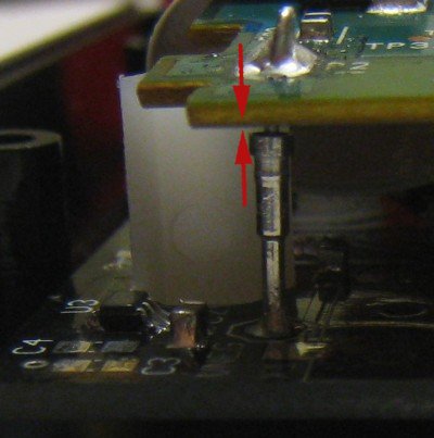
Now begin to position the remote module with the attached cable over the ps3toothfairy. The flat cable should not be folded, but will go between the ps3toothfairy circuit board and the module. You want to position the two pins from the remote module over the sockets on the ps3toothfairy circuit board. Make any small adjustments needed but do not apply force to either of the pins. The pins and sockets will adjust slightly to fit. Verify that both pins are mated inside the sockets.
-
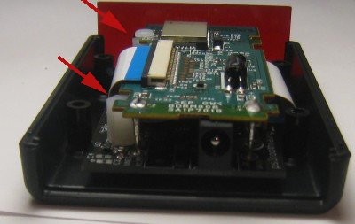
All of the electrical connections have been made, and now you can use the included nylon (white colored) screws to hold the remote module in place. Hold the module with your finger. The module notches should line up with the threaded holes. Insert a screw into each hole and gently screw the nylon screws into place. DO NOT force the screws, just tighten them until the stop turning. Inspect your work and make sure the screws are seated correctly.
-
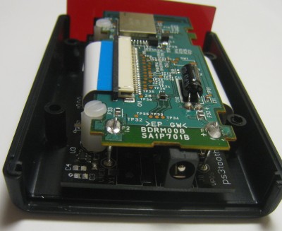
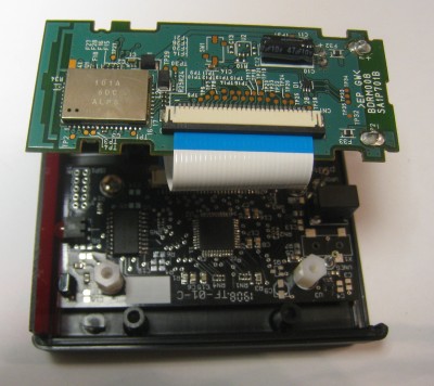
When you have completed the internal assembly, this is what your device should look like. Inspect your work to make sure your cable is properly attached, the screws are fully seated, and the pins are mated to the sockets.
-
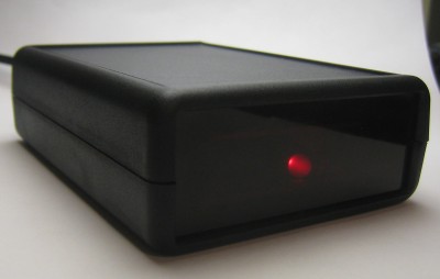
If you want to test the ps3toothfairy before screwing the chassis together, now is a good time. Insert the back plate (and the front RED IR plate if you removed it) and just use a rubber band to hold the chassis together. Plug in the power and the LED on the front should instantly illuminate. It will stay on for about 10 seconds and then turn off. That is a good sign that things are working as expected. Screw the chassis together using the black chassis screws.
-
Power up your ps3toothfairy, congratulate yourself, and follow the normal operating manual for configuration, pairing, and operation. Congratulations!